Does Mostly Compute: Complex Cast
- Jax Whitham
- Apr 20, 2025
- 4 min read
Updated: May 1, 2025
Overview
Individuals seeking to make parts for assembly are often enabled by 3D printers. Those seeking parts not made from printed plastic, and also have access to 3D printers may consider CAD enabled mold making and casting. Hand producing molds is often a frustrating, labor intensive process, specifically when three or more parts are needed. Using Grasshopper, this project aims to take in complex geometries, generates part lines, section a part shell into a mold, and bakes into Rhino for 3D printing. The printed parts are then physically assembled and ready to cast the original geometry as silicone.
Mold Making Process Overview
Here's a good general overview of mold making.
Part lines
Making a two part pour mold involves almost completely encasing the original artifact between two mold pieces--generally made from silicone, plaster or similar materials. The mold will be split on a part line, dictating where the two sections of mold interface and how the produced part will be removed. General guidance in making a part line is to avoid undercuts (a geometry that creates an over hang, making a part difficult or impossible to remove).
Pour Spout and air vents
Because two part mold encase the part, addition opening have to be made to place material in the mold and allow air to escape as it fills. Generally, these ports should be at locally and globally highest points ion the mold. Complex objects often need multiple air vents for individual high spots.
Casting
After the desired mold is complete, apply a mold release agent to the interior, tightly join the two parts together, and pour in your selected material. A cure time later, you will have a nearly identical part.
3D printed mold validation
As an early validation of this project, a two part mold was hand modeled, 3D printed, and used to cast an octahedron in silicon. The parts were produced using generic PLA and the casting materials was Smooth-On Mold-Star 30.
Program Operation
The program operates by taking in a mesh of the object chosen to be cast. From there a bounding box is constructed then expanded slightly to create the external shell of the mold and allows the casting to sit flat while setting. For the internal mold faces, the input mesh is analyzed according to the angle resultant between the normal of each face and the Unit Y vector.


From there the mesh is divided by comparing the resultant angle being equal to, greater than, or less than an input slider angle (anywhere from 0 to 2π, above). The resulting icosahedron mold is two pieces.


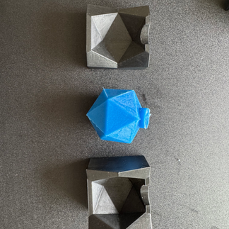
An alternative approach to this splitting has been instituted to force a three part mold. This method uses the division of the unit circle in to fifths and compares each angle to the produced range of values to split the mesh. This forced the test icosahedron mold to be three parts.
The edges of resulting split meshes are used to create a split line that propagates through the external box shell and splits it. Through a series of boolean appropriate mold parts ares produced and then baked into rhino for printing.
User set parameters include: initial geometry as a mesh, pour hole placement, scaling factor of part lines for as successfully cutting surfaces, and optional mesh diving angle.
Fabrication
After printing the produced mold, cover interior surfaces in a think layer of petroleum jelly-- a release agent. Shared faced receive a more generous layer, not so thick excess squishes out but enough to seal the mold closed. band the mold with a rubber band so that no part can move. Mix the two part epoxy and pour into the mold opening, carefully tap the bottom of the mold to release air bubble. Once full, let the mold and casting set then remove the cast, was clean and trim the excess material from edges and pour hole. These steps can be seen in the 3D printed mold validation section.
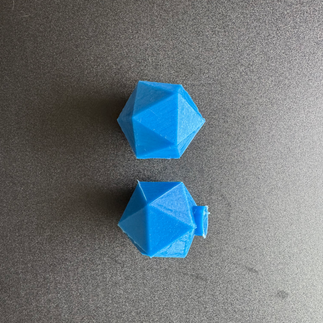
The photos below are the fabrication from both split line division methods used on an icosahedron mesh. The last photo shows the before and after of trimming the cast.


Reflection
This project is on the shallow end of what I was hoping to achieve. Platonic solids taken into the program produce fairly good molds, mainly due to their large faces. I got nowhere near complex geometries as hopped. The project was more difficult than I anticipated. Pull angles to assess how the mold could be separated were the main underestimated elements. Setting the pull angle to an arbitrary line or unit vector really only set the part line up well for one piece of a mold. Its a good start and getting to the a programs full ideal vision will take a few more weeks of dedicated work. Next steps include gradually working with more detailed meshes, keeping sub-meshes of the same color together, and refining pull angle assessments.
References
Meatmolds: Computation Designs of Silicone molds Geometric algorithms for automated design of multi-piece permanent molds